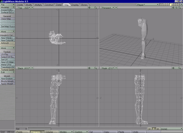
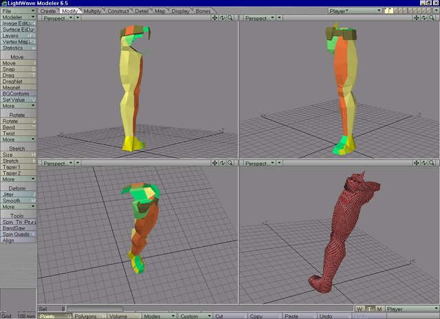
Lets get back to our player object. On this model, legs are symetrically modeled and will have same texture applied on them. Same is with boxes around vaist and feet. Save object or make copy of it in another layer (Lightwave specific). Delete object parts that are symetrical. After cuting and layer aragment i left with situation like on Image08.
|
| Image 08 |
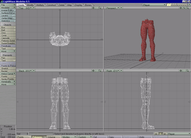
Next step is to surface parts that will be separatelly mapped (like belt, leg, belt buckle, foot) for easier selecting and manipulating. In image09 you can see i assign different surfaces on different parts and arranged them in layers.
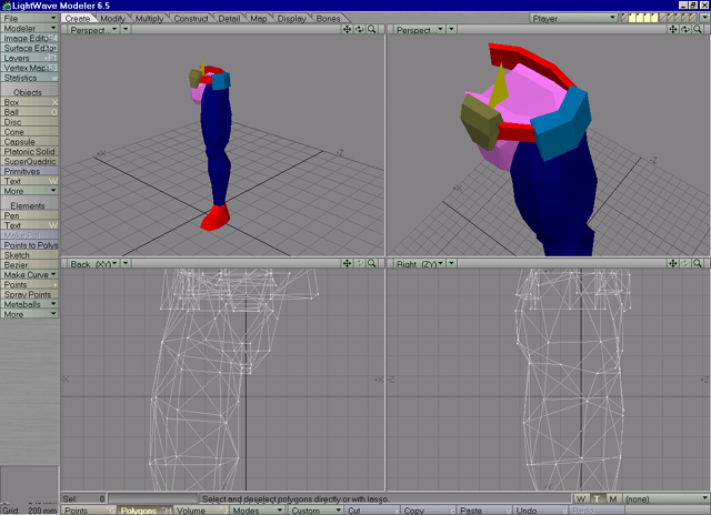 |
| Image 09 |
Ill first map ammoboxes that are placed around vaist (cyan color in Image09). I decided to make seam in back of boxes (polygons that are oriented inside body, because they wont be seen at all. Knowing rule about mapping and importing in Serious Modeler i assign another surface for polygons back (Image10).
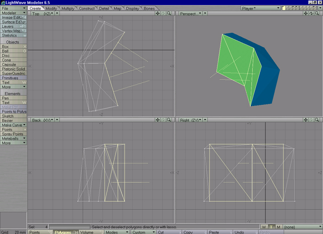 |
| Image 10 |
Since most of polygons in box are faceted in X axis, apply planar UV mapping with X axis selected (Image11).
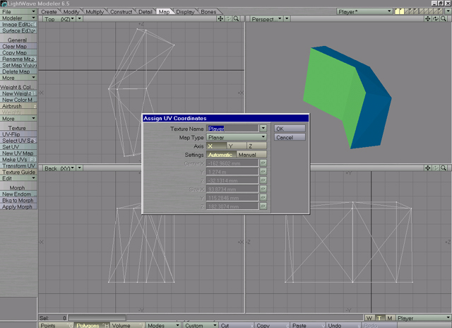 |
| Image 11 |
Change name of UV map and leave other options as default. In surface editor, select those 2 surfaces and add UV projection for Color chanel (Image12).
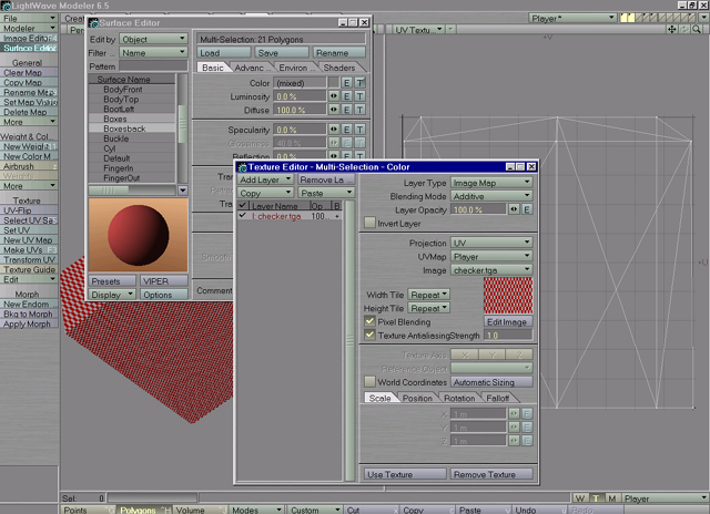 |
| Image 12 |
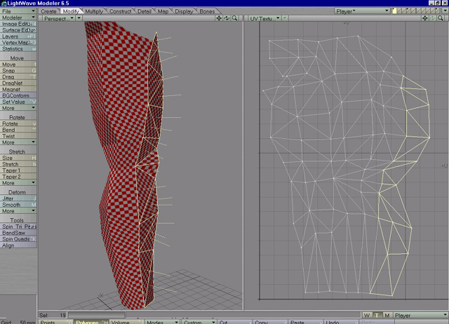
I have prepared checker texture (quadratic red-white checker) for mapping testing. When you apply it as texture map on object, you can easily check mapping stretching or wierdness in mapping. Check Image13, with checker texture applied, you can see how mapping is shrinked on U axis in mapping window (right window). To corect that, put mouse pointer in UV window, activate stretch tool (h), click LMB and drag mouse to right until checker in mapping becomes quadric.
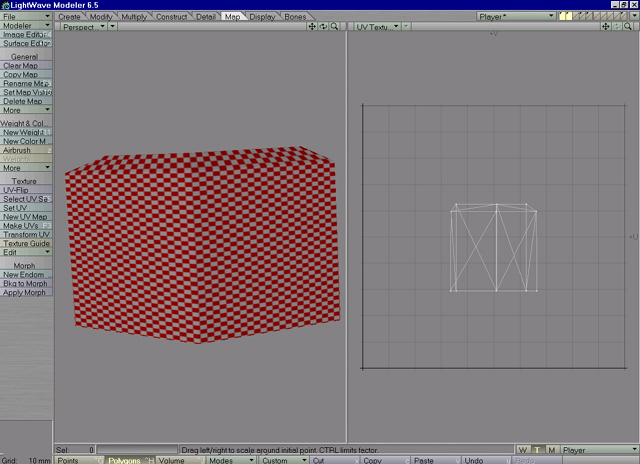 |
| Image 13 |
With planar uv mapping, some stretching in mapping occured. Image14 shows stretching on polygons that are ortogonal or under large angle to axis you are mapping on.
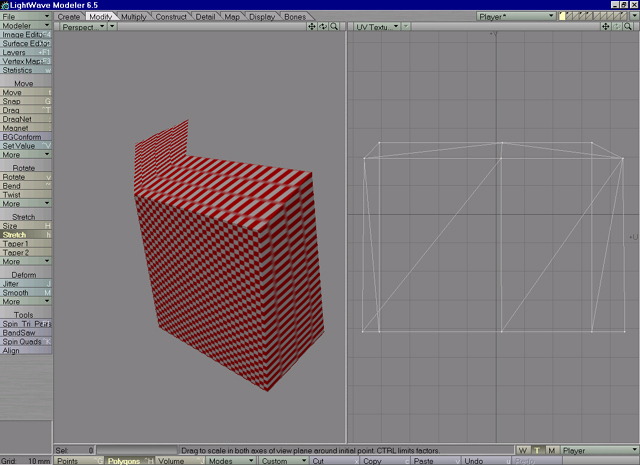 |
| Image 14 |
To correct that, select 3 points on top in mapping and move them up (Image15).
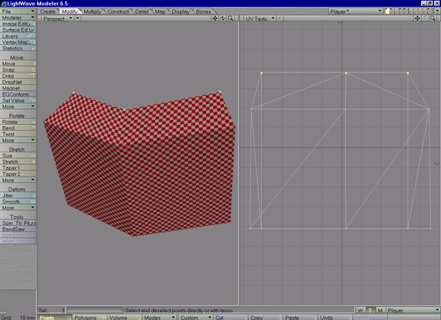 |
| Image 15 |
Repeat same for bottom and side polygons which are stretched.
Another approach you can take to avoid stretching is to detach top and bottom polygons. Image16 shows box mapped with polygons detached. With this mapping, stretching is avoided but seams in mapping are created.
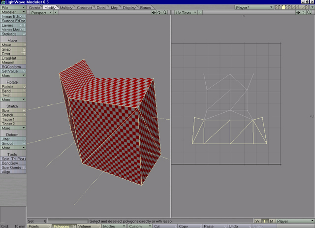 |
| Image 16 |
Next step involves mapping of leg. Leg in this case is extracted from rest of object so it can be mapped cylindrically (Image17).
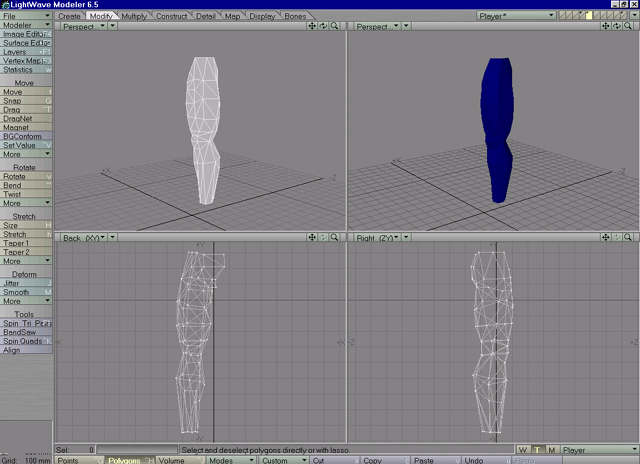 |
| Image 17 |
Apply cylindrical UV mapping (Y axis), leave other options as default. In Surface editor apply to leg's surface UV projection, with correct vmap name and texture (checker for testing). Mapping is stretched on some places, maybe squished, but its easy curable. When you assing UV coordinates, Lightwave tends to lock some vertices from moving. Image18 shows those vertices.
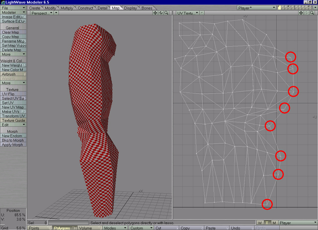 |
| Image 18 |
Though they appear in mapping, you cant move them or edit, unless you unweld them. Select polygons that include those points (row of polygons left of them) and run "unweld" tool. It will detach points and allow their manipulation. This comes crucial when adjusting mapping or moving parts of mapping somewhere else. When fixing mapping, i have 2 window viewport setup, left is perspective with texture, right is UV Texture window. In left window select polygons that have stretched texture and those polygons will be selected in UV map also. Activate drag tool or move tool and move points in mapping to adjust positions. If checker on polygons is to small, it means those polygons have to much space in mapping, same if checker is to big, there are to less space in mapping for those polygons. For leg, i decided to have seam inside of leg, which is hardly seen anyway. With Lightwave UV edit features, editing (adjusting positions and eliminating stretching) of mapping is a lot easier.Image19 shows seam inside of leg. When happy with adjusting merge vertices (it wont mess your mapping).
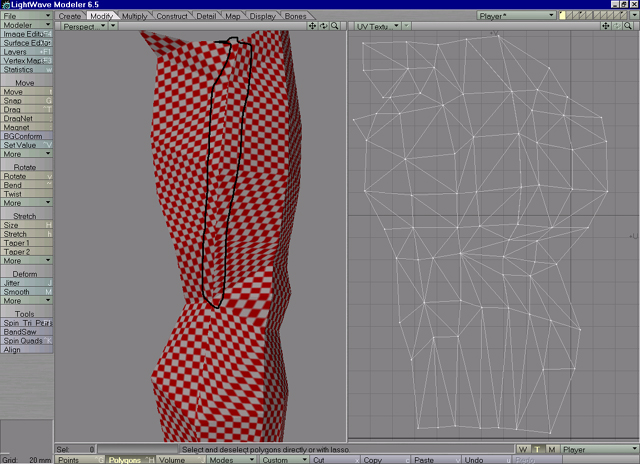 |
| Image 19 |
Same as we did for ammobox, we need to do for leg, we need to add new surfaces on seam so leg will be properly imported in Serious Modeler. Select polygons on seam (Image20) and add new surface on them (like LegSeam).
 |
| Image 20 |
You need to assign Uv projection in surface editor on newly created surface (Image21).
 |
| Image 21 |
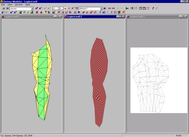
Copy this object, paste it into new document and save it as legtest.lwo. Create new model in Serious Modeler from this object. Image22 shows mdl created with corect mapping.
 |
| Image 22 |
Repeat process of mapping for other parts of object and arange mapping so there are no big gaps between mapping vertices, like on Image23.
 |
| Image 23 |
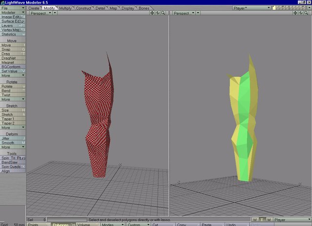
On image24 you can see object surfaced and ready to be mirrored and saved for importing. To show more clearly importance of proper surfacing, i resurfaced object so seams can be easy visible.
 |
| Image 24 |
After assigning surfaces its time to mirror leg part. Select polygons (surfaces) in leg and mirror them on Z axis. If object is symetrical, points should be merged automatically. Image25 shows object mirrored and ready for importing in Serious Modeler.
 |
| Image 25 |
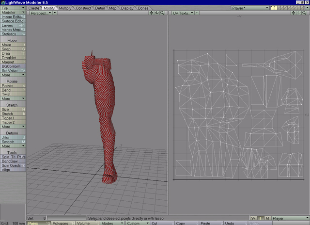
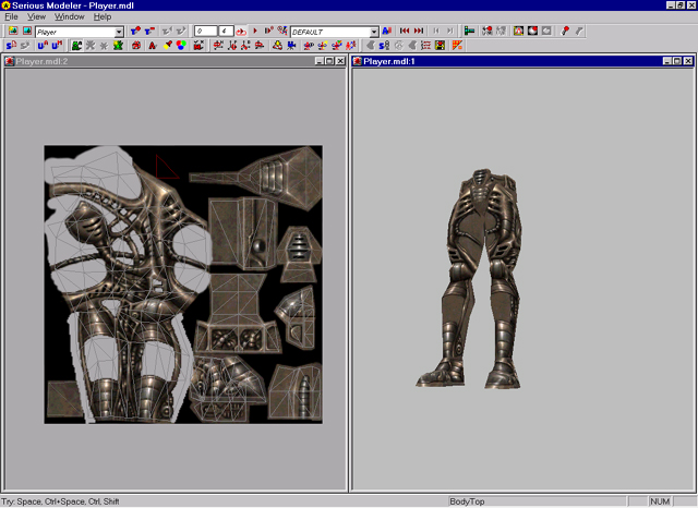
In Serious Modeler from file menu (or CTRL N shortcut) select New and point to player.lwo object. Object should be imported, save it with CTRL S shortcut (or Save from File menu). Press m shortcut to open mapping window. There you can check is mapping imported properly. Image26 shows Player model and mapping window.
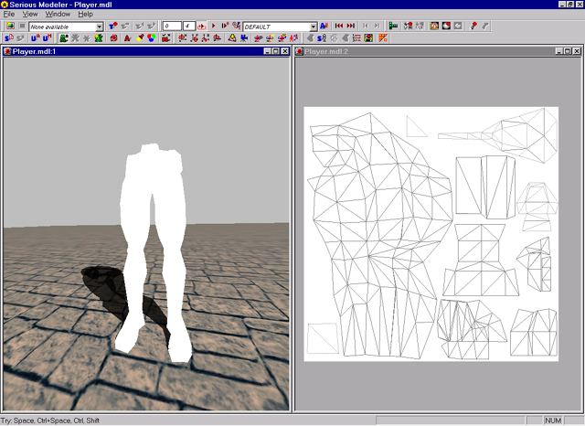 |
| Image 26 |
When you import 3d object in Serious Modeler, in object's folder, script file (.scr) with object name is created. From Serious Modeler you can acess and edit script by pressing s shortcut. Bellow is script created for player model.
;******* Creation settings
TEXTURE_DIM 2.0 2.0		-dimension of texture for model in texels.
SIZE 1.0			-model stretch, higher number, the bigger model in meters.
MAX_SHADOW 0			-shadow quality
HI_QUALITY YES		-high quality means lower compression and less distortion on model
FLAT NO			-use this option for plane models that will be used as explosions, smoke effects..
HALF_FLAT NO			-use this option for plane models that will be used as torches, fire effects....
STRETCH_DETAIL NO		-if model is stretched, you can stretch its bump/detail texture

;******* Mip models
DIRECTORY Models\Tutorials\Tutorial01\Player\StainlessSteve\
MIP_MODELS 1			-number and list of LOD models created for this model
    Player.lwo

ANIM_START
;******* Start of animation block

DIRECTORY Models\Tutorials\Tutorial01\Player\StainlessSteve\
ANIMATION Default
SPEED 0.1
    Player.lwo		-default animation, created by default once object is imported in Modeler.

;******* End of animation block
ANIM_END
END
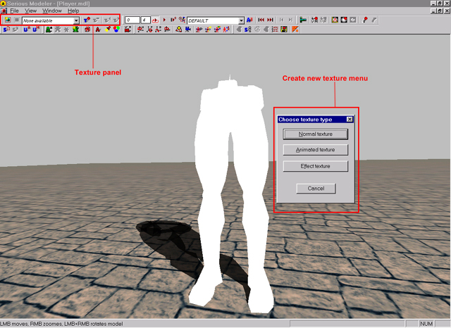
When creating model from 3d object, if texture (.tex) with object name exists (like player.tex) it will be automatically loaded. Otherwise you need to add it manualy. To test model and its mapping lets create and add checker texture we used in Lightwave as mapping guide. Click CTRL SHIFT T shortcut or from Texture panel click on Create new texture button. Menu with 3 options will open (Image27).
 |
| Image 27 |
From there you can select to create:
"Normal texture" -single image texture (with alpha chanel or without), used for maping weapon, player and similar models.
"Animated texture" -image sequence used for explosions, smoke or particle effects.
"Effect texture" -procedural texture used for water, fire, waterfall and similar effects.
For this model we wil use Normal texture, click on Normal texture button or n shortcut. Requester will open asking you to select .tga image that will be converted into .tex file suitable for Serious Modeler. Double click on checker texture in requester, additional properties will be presented for you (image28).
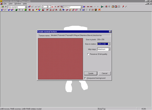 |
| Image 28 |
Left in panel texture is displayed, size in meters coresponds to TEXTURE_DIM variable in model's script (if size in meters is smaller than TEXTURE_DIM, texture will tile on model, If size is bigger, texture wont whole fit on model's mapping). Mip maps tels how many mipmaps to create for this texture. Mipmaps are way to scale texture's dimension down when model with that texture is moving away from viewer. Sometimes you want to create only one mipmap (for textures that will be used as fake lightsources) to prevent bilinear algorithm in destroying texture content. When texture have alpha chanel, its quality is reduced in expence of memory it occupies. If quality isnt satisfactory check on "Preserve 32-bit quality" checkbox and texture will be saved as 32bit but it will take more memory. Use this on textures with gradients or alpha chanels, like Background textures, explosion effects and similar. In bottom of panel is "Use chequered background" button, usefull when checking texture's alpha chanel.
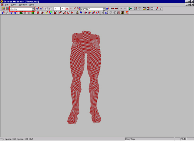
Click on "Create" button,texture will be created and loaded on model (image29). Save model to preserve texture's path into model file.
 |
| Image 29 |
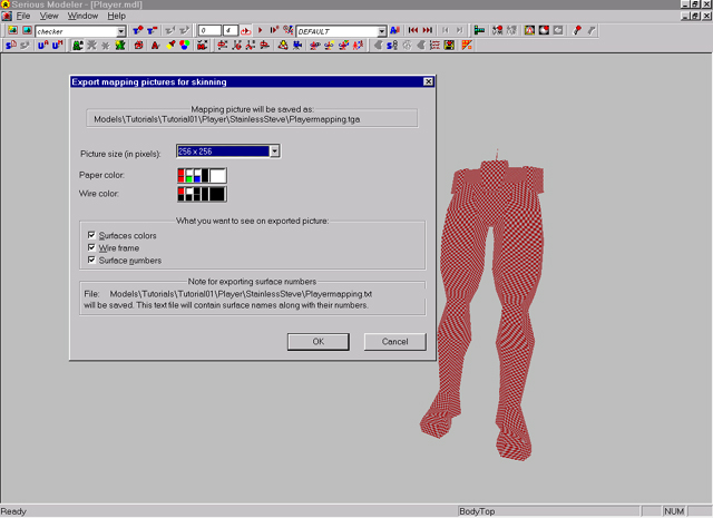
In Texture panel, texture name will appear. You can add as many textures as you want, they will appear in texture panel for browsing, or use PageUp, PageDown shortcuts to browse thru loaded textures. Rotate and examine model (check Navigation part in Serious Modeler). If you make any changes to object, simply recreate model (CTRL SHIFT S). Change rendering options (wireframe,surfaces...) to examine model. If you are happy with how model looks, its time to export mapping into tga file for texture painting (though it can be done in any 3d application). Serious Modeler's export mapping offers additional options. From File menu select "Export for skinning option", requester will open asking you give name of to be saved image. After that Exporting properties panel opens (image30).
 |
| Image 30 |
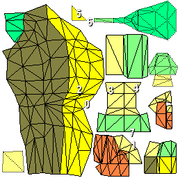
On top path and name are displayed. With "Picture size" you can define pixel size of texture. Paper color defines background color, while Wire color defines color of wirframe mesh. Additionaly insted of empty wireframe, mapping can be flatfiled with surface color. Wireframe enables wireframe mapping to be saved. If you select "Surface numbers" option, text file with numbers and surface names will be saved and numbers will be added above surfaces in mapping texture. Image31 shows exported mapping for player model.
 |
| Image 31 |
Create new texture from this image for easy editing. Load that image into your paint program and paint model's texture in it. When you finish painting or want to check paint progress,save image and in Serious Modeler click CTRL SHIFT R shortuct to recreate texture. It will load image from disk that texture is created from and update texture.
Its time to take a look at rendering and texture blending options available in Serious Modeler. Image32 shows texture made for this model.
 |
| Image 32 |
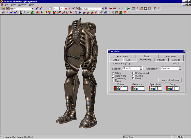
In mapping view you may noticed holes in texture (where grey background is visible). This is because texture have alpha chanel, Modeler automaticaly displays texture with alpha chanels. We will now apply alpha chanel blending on model using per surface blending. Click Q shortcut to open Tools panel and click on Rendering tab (for more information check Tools window part of Serious Modeler Help).
 |
| Image 33 |
This model is designed to have transparent parts of its geometry (thus texture with alpha chanel). Serious Modeler have per surface editing approach for texture blending and rendering options. This means that you can assign number of surfaces in your 3d program and individualy or multiple edit them in Serious Modeler.
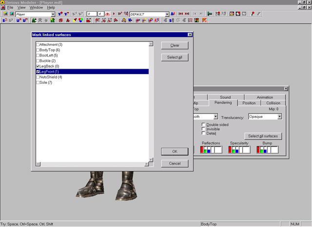
In rendering panel you can cycle thru defined surfaces with Tab and Shift Tab shortcuts. Lets start with legs first, cycle in rendering tab until Leg surface (or how you called it in 3d program) becomes active. Another approach is to run Link surfaces tool (Z) shortcut and select multiple surfaces for editing (Image34).
 |
| Image 34 |
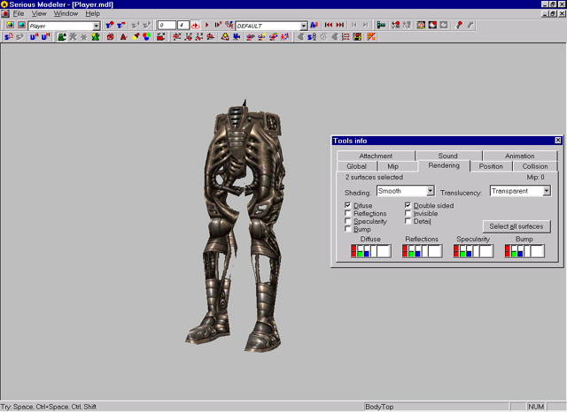
Select surfaces you want to edit and press OK. In Rendering panel name of active surface will change to number of select surfaces. Quick check selection by clicking on invisible button (they wont render). Disable invisible option, for Transluscency select Transparent option (use alpha chanel). Also enable Double sided option. Model should look like on Image35.
 |
| Image 35 |
Another thing we want to add on model is specular texture (since model have metalish texture, specular and reflection effects are calling). With leg surfaces selected, in Rendering panel check on Specularity buton. Nothing changes since we dont have Specular texture loaded. You can create your own specular texture, or loaded predifined one (for more on Specular texture check Add Specularity section in Serious Modeler Help. Click on "Browse specular texture" in FX control panel and load Medium.tex from models/SpecularTextures/ folder.
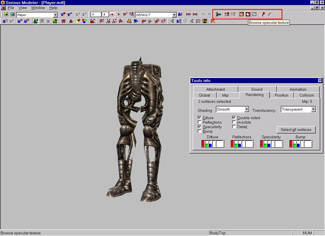 |
| Image 36 |
Hold Shift Both mouse buttons and rotate mouse to roate light around model and see how specularity changes on model. You can also hold Space Both mouse buttons to rotate model and see specular effect.
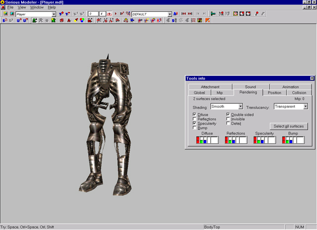 |
| Image 37 |
By default specular color and strenght is white. For this model we will change it to more orange color (to simulate sun reflacting on metal). Use HSV sliders bellow specularity or double click on white box to change color. We ended with something like on Image38.
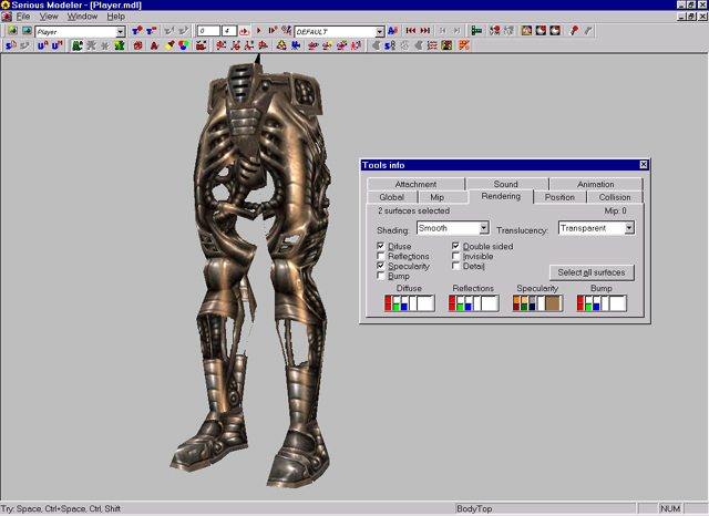 |
| Image 38 |
Same as we add specular we can add reflection or bump. Note that every of those effects have impact on rendering time !
Next step is adding Colision properties.
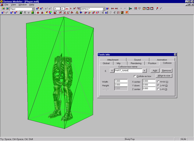
In Tools panel click on Collision tab and press c short to enable collision box rendering (For more information on collision refer to Collision box section in Serious Modeler Help). Image39 shows default collision created with model.
 |
| Image 39 |
For multiplayer models, 3 collision boxes are needed. Change PART_NAME line to STAND (this will represent collision when player is runing, walking etc...). Also change Height to 2.2 (numbers here are arbitrary, you can change them to fit your model). Collision represents collision of whole model not just legs. Another 2 collision will be added once we add all attachments and animations.